

12 mins
The End to End Product Development Loop: An AI Agent Workflow October 2026
Watch an AI agent take a requirements PDF through SOLIDWORKS parts, a GD&T drawing, Ansys results and Rev B, flagging every gap. (October 2026)
Bryce Heventhal

An AI agent takes a design brief through SOLIDWORKS parts, an assembly, a GD&T drawing, Ansys Mechanical results and a Rev B iteration, and flags every place the brief doesn't add up
TLDR:
One AI agent carried a fuel cell stack from a requirements PDF through SOLIDWORKS parts, a GD&T drawing, Ansys Mechanical results, and Rev B.
The agent flagged 5 spec conflicts, including a clamp load mismatch of 217 kN vs. 60 kN in the brief, and logged each as a deviation.
Outputs are equation-driven and editable: Rev B is a parameter change, not a rebuild from scratch.
Judge any CAD-to-FEA agent on the deviations it discloses, not on whether it reports a clean run.
Cosmon's Argus agent runs natively across SOLIDWORKS and Ansys, retains no customer data, and is SOC 2 compliant.
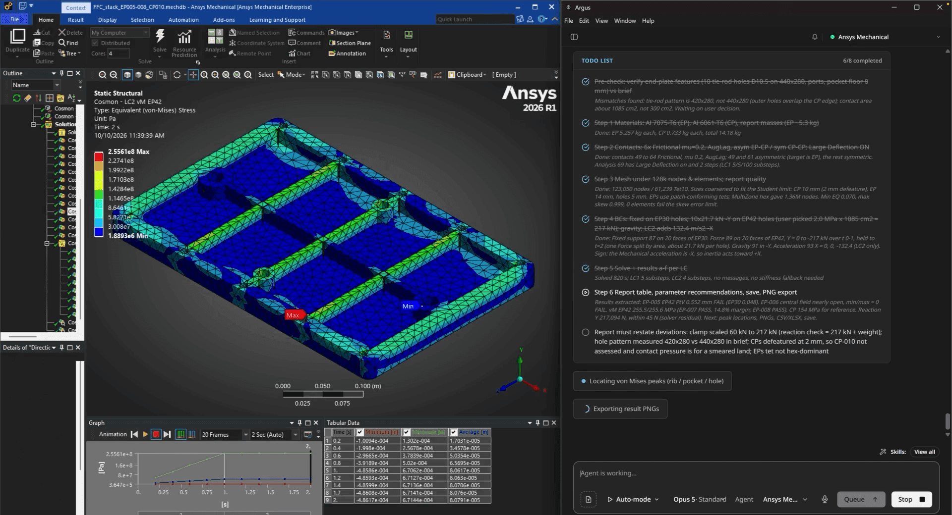
Argus works through its Ansys task list beside the von Mises stress result for the end plate.
The handoff problem
Here is a familiar week. A requirements document lands with loads, a material, an envelope and a few part rules. Someone models the plates in SOLIDWORKS. Someone else, or the same person on a different day, rebuilds the setup in Ansys from the spec. The results raise a question, the geometry changes, and the drawing falls a revision behind.
None of those steps are hard on their own. The cost is in the handoffs: every time intent moves from one tool to another, it is re-typed, re-interpreted, and sometimes quietly changed. By the time a design reaches Rev B, nobody can say with confidence which assumptions the simulation actually used.
That is the problem this demo is about. Not "can an AI draw a plate," but whether one agent can carry the design intent across SOLIDWORKS and Ansys and leave a record a reviewer can trust.
What "end to end" actually means here
"End to end" gets used loosely, so here is the scope of this run:
Inputs: a requirements PDF and a structured requirements file for a flying fuel cell stack.
Outputs: equation-driven SOLIDWORKS parts for an end plate and a cooling plate, a stack assembly, an A3 drawing with GD&T, an Ansys Mechanical static structural model with results and exported plots, and a Rev B of the end plate with the drawing updated to match.
What a human did: answered the questions the agent asked, and wrote the brief for the iteration.
Method 1: Do it the usual way
The manual path is well understood:
Model from the spec. Read the requirements, build the parts, and hope every dimension came from the current revision of the brief.
Assemble and detail. Build the stack, then the drawing: views, sections, datums, tolerances, title block.
Rebuild in simulation. Import the geometry into Ansys Mechanical, assign materials, define contacts, apply loads and supports, mesh, solve.
Carry decisions back. Update the model and the drawing when the results say the design needs to change.
Each step is skilled work. The weak point is that the checks between them live in people's heads. If the load in the brief doesn't match the geometry, the person setting up the simulation may notice, or may not.
Method 2: One agent across SOLIDWORKS and Ansys
The alternative is an agent that operates both tools directly. The distinction we keep coming back to is between a copilot that suggests what to click and an agent that performs the operations in the tool and reports what it did. We cover that difference in AI for SOLIDWORKS copilots and agents.
What the agent did, tool by tool
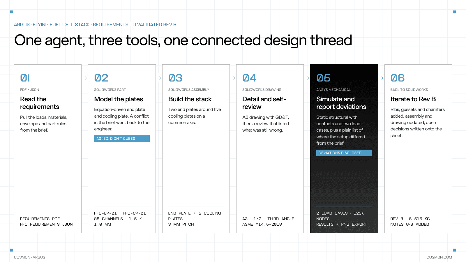
Read the requirements. Argus took the requirements PDF and the structured requirements file as its source of truth for loads, materials, envelope and part rules.
Modeled the plates in SOLIDWORKS. It built the FFC-EP-01 end plate driven by equations, so that changing rib count or pocket floor thickness rebuilds the geometry, then started the FFC-CP-01 cooling plate. When the cooling-plate drawing contradicted itself, it stopped and asked (more on that below).
Built the stack. Asked for an assembly, it offered arrangement options and built a short stack: an end plate, five cooling plates at 3 mm pitch, and an end plate, on a common axis.
Detailed and reviewed the drawing. It produced an A3, 1:2, third-angle drawing to ASME Y14.5-2018, with a top view, a section through a coolant boss, an isometric, datums A to C, positional tolerances on the hole patterns, flatness and parallelism. It then reviewed its own sheet and listed what was still wrong, including a missing boss-height dimension, decimals that clashed with the title-block tolerance, and crossing leaders. More on this step in our guide to drawing automation AI for SOLIDWORKS.
Simulated in Ansys Mechanical. It assigned materials, set the contacts to frictional, and ran a static structural analysis with large deflection and two load cases, then exported deformation, stress and contact-pressure plots and a results workbook.
Iterated to Rev B. Given a brief to stiffen the end plate, it added ribs, gussets and corner chamfers driven by new global variables, regenerated the stack, and updated the drawing: dimensions re-created on the new edges, obsolete ones removed, and new notes added for the open decisions.
Watch it happen: https://youtu.be/F5-EHMz5-18?si=RltsGBGZ4vZPxYZ0
Argus takes a fuel cell stack from a requirements PDF to SOLIDWORKS parts, a GD&T drawing, Ansys Mechanical results and Rev B, asking and flagging wherever the brief doesn't add up.
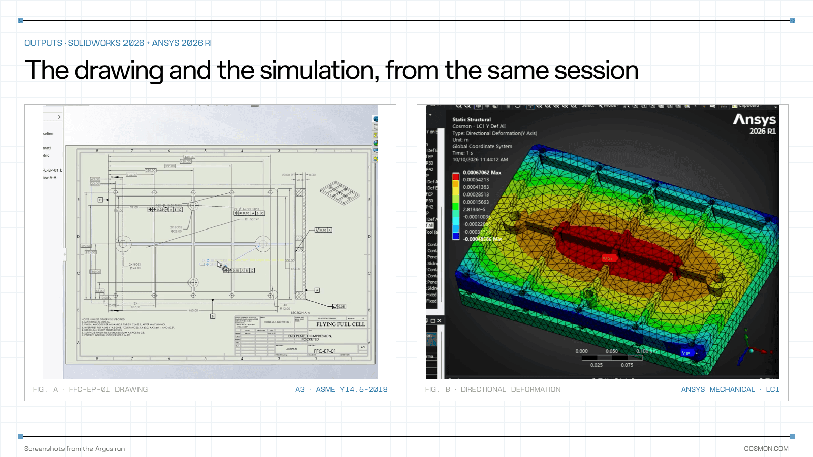
The drawing and the simulation came out of the same session, from the same design intent.
Where the brief didn't add up
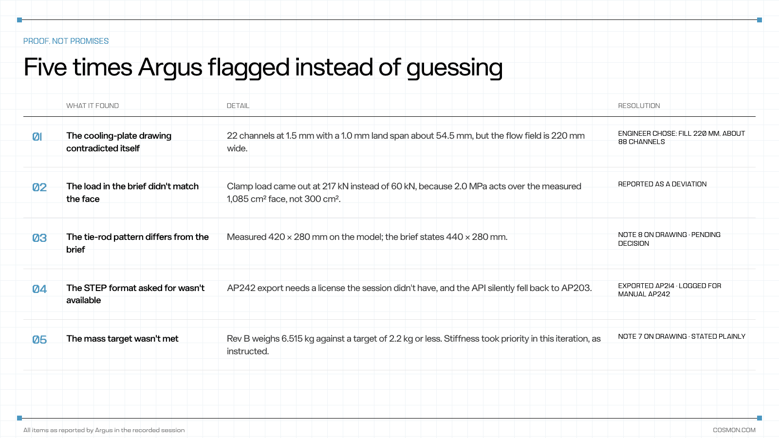
This is the part of the video we'd ask you to watch closely. Real design briefs are inconsistent, and a system that never reports a problem isn't more capable, it's less honest. In this run Argus flagged five:
Conflicts between the brief and the geometry
The cooling-plate drawing contradicted itself. Twenty-two channels at 1.5 mm with a 1.0 mm land span about 54.5 mm, but the flow field is 220 mm wide. Argus asked which to build. The engineer chose to fill the 220 mm field, about 88 channels.
The clamp load didn't match the face. Applying the specified 2.0 MPa over the measured 1,085 cm² face gives 217 kN, not the 60 kN in the brief, which assumed 300 cm². Argus ran it and reported it as a deviation rather than silently picking one.
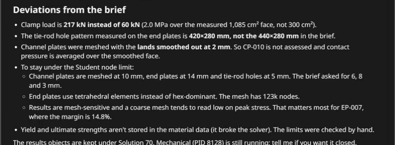
Argus's own "Deviations from the brief," reported alongside the results.
The tie-rod pattern differed from the spec. The model measured 420 × 280 mm; the brief states 440 × 280 mm. Argus wrote the open decision onto the drawing as a note instead of changing either one.
Limits the agent hit along the way
The requested STEP format wasn't available. STEP AP242 export needed a license the session didn't have, and the API quietly fell back to AP203. Argus caught the fallback from the file header, exported AP214, and logged that AP242 needs a manual export.
The mass target wasn't met. Rev B weighs 6.515 kg against a target of 2.2 kg or less. The iteration brief said stiffness took priority, and Argus stated the miss plainly on the drawing instead of burying it.
How the simulation setup was disclosed
It was equally explicit about the simulation setup itself: where mesh sizes were coarser than the brief asked for, which elements were used, and that coarse meshes tend to read low on peak stress. That is exactly the context a reviewer needs before trusting a margin.
Comparison
Factor | Manual handoffs | Single-tool suggestions | One agent across SOLIDWORKS and Ansys |
|---|---|---|---|
Who carries design intent between tools | People, by re-reading the spec | People | The agent, from one source of truth |
Spec conflicts | Caught if someone notices | Not in scope | Surfaced as questions or written deviations |
Drawing kept in sync with model | Manual, often a revision behind | Manual | Updated in the same session |
Simulation setup record | In the analyst's notes | None | Reported with the results |
Effort on you | Every step | Every step, with hints | Answer questions, review the record |
What to check in any end-to-end CAD and FEA run
One source of truth for requirements. Every load, material and dimension should trace back to the brief, and the run should say where it couldn't.
Native, editable outputs. Feature trees driven by variables, not dead solids, so Rev B is a parameter change rather than a rebuild.
A drawing that reviews itself. Datums, tolerances and callouts checked against the standard, with the open issues listed.
A disclosed simulation setup. Mesh sizes, element types, contacts and load cases stated next to the results, along with how they differ from the brief.
Honest iteration results. When a target isn't met, the record should say so and why.
Where this matters most
Early design loops. When the brief is still moving, an agent that surfaces conflicts on day one saves a redesign on day ten.
Small teams covering both CAD and CAE. If the same engineer models and simulates, the handoff overhead is pure cost. More in our evaluation of AI agent use cases for mechanical engineers.
Programs that need traceability. Requirement IDs carried into file properties, deviations written down, and decisions noted on the drawing make reviews faster and audits less painful.
A note on your data
Requirements documents and native CAD files are among the most sensitive things an engineering team owns. Ask any AI vendor where your files go, who can see them, and whether they are retained or used for training. Cosmon is SOC 2 compliant and retains no customer data: zero data retention in the cloud, or fully on-prem. More in adopting AI securely without risking engineering IP.
Final thoughts
The interesting question about AI in engineering was never whether it can extrude a plate. It's whether it can carry design intent across the tools you already use without losing it, and tell you honestly where it couldn't.
In this run, the most valuable outputs weren't the parts or the plots. They were the five places the agent stopped, asked or wrote down a deviation. That record is what lets an engineer review an agent's work in minutes instead of redoing it.
FAQs
Can an AI agent work in both SOLIDWORKS and Ansys?
Yes. An agent like Argus operates SOLIDWORKS and Ansys Mechanical directly, creating parts, assemblies and drawings in one and setting up and solving the analysis in the other, from the same requirements.
How do you transfer a SOLIDWORKS model to Ansys Mechanical?
Typically through a native CAD connection or a neutral format such as STEP, then re-applying materials, contacts, loads and supports in Mechanical. The risk is that assumptions change in transit, which is why a written setup record matters.
Can AI create a SOLIDWORKS drawing with GD&T?
It can produce views, sections, datums and tolerances to a standard such as ASME Y14.5-2018 and fill in the title block. A good agent also reviews the sheet and lists remaining issues, like missing dimensions or crossing leaders, for a human to resolve.
What happens when the design requirements conflict?
A trustworthy agent should stop and ask, or proceed and report the deviation. In this demo, Argus asked about a self-contradicting cooling-plate drawing and reported that the brief's clamp load didn't match the geometry.
Does the agent replace the engineer's review?
No. It changes what the review looks like: instead of re-checking every step, the engineer reviews the decisions and deviations the agent recorded, and makes the calls that need judgment.
Creating accurate GD&T drawings has always been one of the most time-consuming tasks in mechanical design. Nexus reads your geometry and generates fully production-ready engineering drawings instantly without manual effort. Creating accurate GD&T

Bryce Heventhal
SEE RELATED ARTICLES