

10 min read
How to Convert a 2D Drawing to a 3D Model in SOLIDWORKS
Compare three ways to turn a 2D drawing into a 3D SOLIDWORKS model: the built-in 2D to 3D toolbar, outsourcing, and an AI agent working inside SOLIDWORKS.
Bryce Heventhal

TL;DR
SOLIDWORKS has a built-in 2D to 3D toolbar. It imports DWG or DXF geometry as sketches and gives you commands to turn those sketches into features. It works, and it is entirely manual — you align each view yourself and define every extrusion by hand.
The hard part is not extruding. It is interpretation. A legacy print carries hidden lines, section cuts, hole callouts, tolerance notes and a title block. Getting those into a model correctly is where the hours go.
Outsourcing moves the cost rather than removing it. You still write the spec, still answer the questions, and still check the returned model against the print — and you wait days instead of hours.
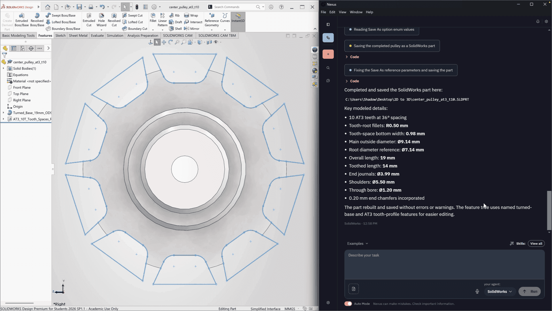
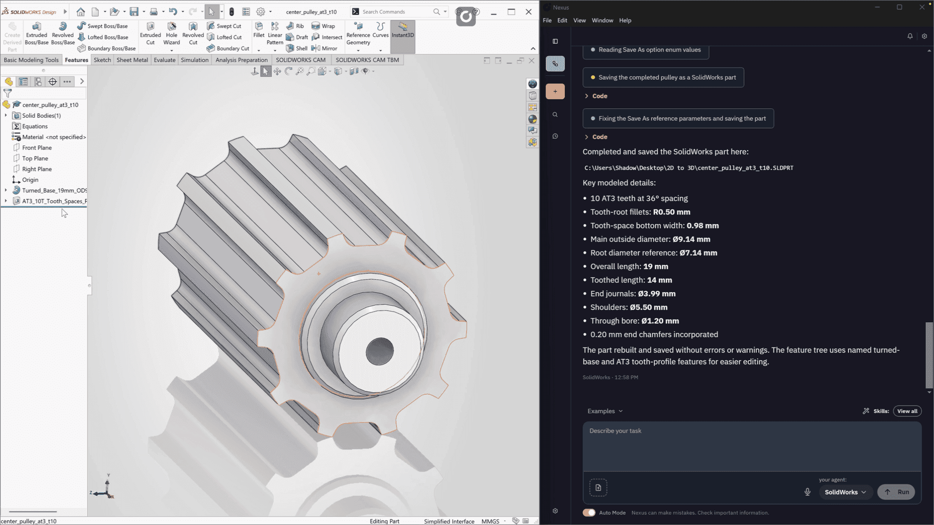
An AI agent working inside SOLIDWORKS can read the sheet and build the feature tree. Not a mesh, not a dead solid: sketches, extrudes, revolves, holes and chamfers you can edit afterward.
Insist on two things from any automated approach: every dimension checked back against the print, and ambiguity flagged rather than guessed. A conversion you cannot audit is a conversion you cannot ship.
Every engineering organization that has been making things for more than a decade has an archive problem. Drawings from the 1980s and 1990s, released and revised and released again, describing parts that are still in production — and that exist nowhere as 3D geometry. The drawing was the deliverable back then. It still governs the part today.
That is fine until something has to change. A customer asks for a larger bore. A supplier discontinues a material. A new variant needs the same bracket 8 mm longer. At that point the work does not start with engineering judgment. It starts with somebody rebuilding a part that was fully designed thirty years ago, so that a one-dimension change becomes possible at all.
This guide covers the three ways teams actually get from a 2D drawing to a 3D SOLIDWORKS model, what each one costs, and — the part most tutorials skip — how to know the model you ended up with is right.
What "2D to 3D conversion" actually means
Two different jobs share the same phrase, and the search results mix them together.
Sketch to solid. You have clean 2D CAD geometry, usually a DWG or DXF exported from AutoCAD, and you want it as a solid body. The geometry is trustworthy. The task is mechanical.
Legacy print to parametric model. You have a released engineering drawing — possibly a scan, possibly with hand-lettered revisions — and you need a native, editable SOLIDWORKS part that matches it and can be changed. The geometry has to be interpreted before it can be built.
The first job is an afternoon. The second is the one that fills backlogs, and it is the one this guide is mostly about.
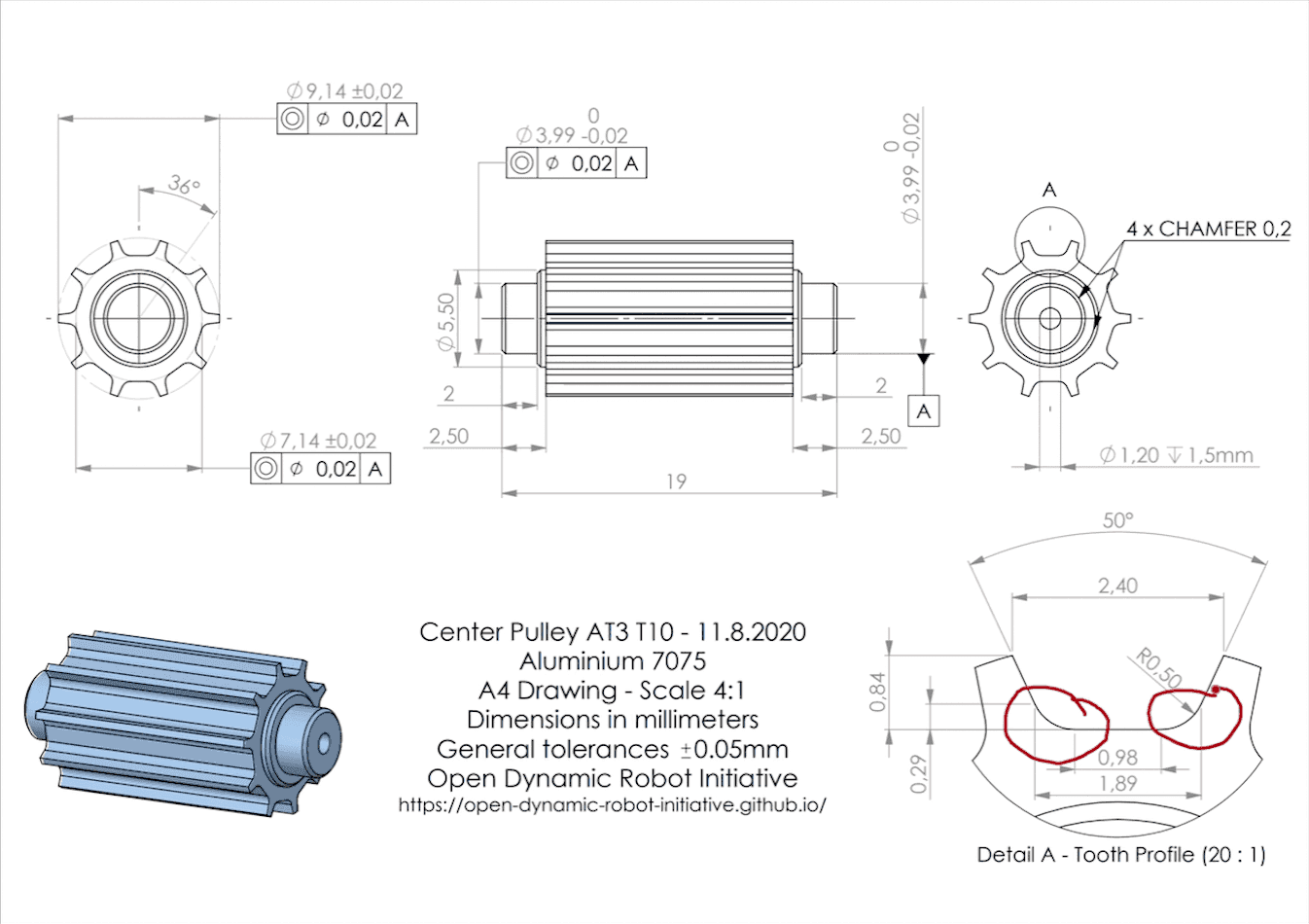
Method 1: The native SOLIDWORKS 2D to 3D toolbar
SOLIDWORKS ships with a dedicated 2D to 3D Conversion toolbar. If your source is a reasonably clean DWG or DXF, this is the right place to start, and it is free with your seat.
The workflow runs in three phases.
Import. Open the DWG or DXF and step through the import utility. Choose Import to a new part as 2D sketch, set your units, decide whether to bring in constraints and dimensions, and select which layers you actually want. You will merge overlapping entities, delete construction geometry and title-block linework, and work through any block-explosion warnings.
Align. Make the imported sketch editable, then align it to the part origin by picking a point. Distribute the geometry into Front, Top and Right sketches using the toolbar's view commands. Then align those views to each other by selecting corresponding edges. This step is where most of the fiddling happens.
Build. Use Convert to Extrusion and Convert to Cut, pre-selecting the sketch geometry for each feature and defining depth by picking vertices in an adjacent view — the "up to vertex" method.
Where it works well: single parts, clean vector source, prismatic geometry, one or two views.
Where it stalls: scanned drawings with no vector data at all, geometry spread across dozens of mislabeled layers, section views the toolbar cannot relate to the ortho views, revolved and swept features, and hole callouts that exist as text rather than as circles. And at the end of it, nothing has checked your work. If you misread a dimension in view B, the model is wrong and it looks fine.
Method 2: Outsource the conversion
A sizeable industry converts 2D drawings to 3D CAD as a service, typically priced per part and quoted in business days.
This is a real option, especially for a one-time bulk migration where the drawings are consistent and the parts are simple. It has three costs that quotes tend not to itemize.
You still write the specification — modeling standards, feature naming, tolerance interpretation, what to do with the title block. You still answer the questions, and on legacy prints there are always questions. And you still verify every returned model against its drawing, because a supplier who has never made your part cannot catch the error where the drawing is ambiguous and the plausible reading is the wrong one.
Outsourcing converts engineering hours into coordination hours and calendar days. Sometimes that trade is worth making. It is not the same as the work going away.
Method 3: An AI agent working inside SOLIDWORKS
The third approach is newer: an agent that operates SOLIDWORKS directly, reads the drawing the way an engineer reads it, and builds the model natively.
The distinction that matters here is between a chat assistant that suggests what you might do and an agent that performs the operations in the CAD system itself. We've written about the difference between a copilot and an agent at length, and about AI for SOLIDWORKS more generally.
Applied to a legacy drawing, the sequence looks like this:
Read the sheet. Identify the orthographic views and how they relate, the section cuts, the hole callouts, the tolerance notes, the title block, the revision history.
Extract the dimensions. Every driving dimension, mapped to the feature it drives — not just measured off the linework.
Map dimensions to features. Decide that this rectangle plus this depth is an extrude, that this callout is a counterbored hole, that this profile plus this centerline is a revolve.
Build natively. Create the features in SOLIDWORKS in the order an engineer would have created them, producing a real FeatureManager tree.
Verify. Measure the finished model and check every dimension back against the print.
Flag, don't guess. Where the drawing is genuinely ambiguous, surface the conflict for a human decision instead of picking a reading silently.
Step 6 is the one to interrogate when you evaluate any tool in this category. Legacy drawings are ambiguous — a radius that could attach to either of two edges, a dimension that conflicts with the section view, a note that references a superseded standard. A system that reports a clean conversion every time is not more capable than the alternatives. It is less honest about what it did.
Watch it happen: [embed the 2-minute video here]
A legacy drawing goes into SOLIDWORKS and comes out as a parametric model, including one flagged ambiguity, resolved by the engineer on camera.
Factor | Native 2D to 3D toolbar | Outsource the conversion | AI agent inside SOLIDWORKS |
|---|---|---|---|
Best fit | Clean DWG or DXF, single prismatic parts, one or two views | One-time bulk migration of simple, consistent parts | Legacy prints and backlogs that must stay editable |
Handles scanned drawings | No, needs vector geometry | Yes, but you pay per part and wait | Yes, reads raster sheets directly |
Output | Native feature tree you build by hand | Varies by vendor, confirm it is parametric | Native parametric feature tree |
Effort on you | Full manual alignment and feature building | Write the spec, answer questions, verify each model | Review flagged ambiguities and check the record |
Turnaround | A few hours per part | Business days plus coordination | Minutes of engineer review per part |
Verification | None built in, you check by hand | You verify every returned model | Dimensions checked back against the print, ambiguity flagged |
Drawings leave your environment | No | Yes, sent to a third party | No with local deployment and no data retention |
What a correct conversion has to get right
This is the checklist to hold any method against, whether you're doing it by hand, buying it, or automating it.
All the views, related to each other
A part is not defined by its front view. Depth, hidden features and internal geometry live in the other views and the section cuts, and a conversion that only reads the most prominent view produces a confidently wrong part.
Hole callouts as features, not as circles. ⌀6.5 THRU, ⌀11 X 90° CSK is a specification. Modeled as a plain circular cut, the counterbore is gone and manufacturing will not know it was ever there.
Tolerances and notes carried forward. GD&T, surface finish callouts, material spec, heat treatment. These do not live in the geometry, and dropping them turns a controlled part into an approximate one.
A parametric feature tree
This is the difference between "we converted your drawing" and "you can now change the part." A dead solid or an imported mesh gets you a picture of the geometry. A feature tree gets you the ability to make the 8 mm change that started the whole exercise, in seconds rather than starting over.
A verification record. Which dimensions were checked, which matched, and which required a human decision. Without it you have a model that looks right, which is the most expensive kind of model to have.
How long does it take?
Honest answer: it depends on the drawing, and anyone quoting a single number across all parts is guessing.
For a moderately complex prismatic part from a clean DWG, manual conversion with the native toolbar typically runs a few hours once you include alignment, feature-by-feature building, and checking the result against the print. Scanned sheets, revolved geometry and heavy GD&T push that up. Outsourcing trades those hours for [X] business days and a coordination overhead.
In our own testing on legacy sheets, agent-driven conversion took a manual remodel of roughly [X] hours down to about [X] minutes of engineer review. Your number will differ, and the only figure worth acting on is the one you measure on your own drawings — which is why we'd rather you time it than take ours.
The multiplier is what changes the decision. One part at four hours is an afternoon. Eight hundred parts at four hours is [X] engineer-years, which is not a scheduling problem, it is the reason the backlog never moves. Cut the per-part time and the backlog becomes finishable.
Where this matters most
Three situations turn a legacy 2D archive from an inconvenience into a constraint.
Customer-driven geometry changes. An ECO arrives against a part with no model. The change is trivial; the prerequisite is not.
Simulation and DfM on legacy parts. You cannot mesh a drawing. Any analysis, tolerance stack-up or manufacturability check on a legacy part starts with getting it into 3D first — and once it's there, the rest of the workflow opens up. This is the same translation gap we've written about between a physical problem and a validated simulation.
PLM migration and consolidation. After an acquisition or a system migration, "get the archive into the new PLM" quietly means "model several hundred parts." That project either gets automated or gets deferred indefinitely.
If you're scoping which of these to tackle first, a real evaluation of agent use cases covers how teams have prioritized.
A note on your drawings leaving the building
Legacy drawings are among the most sensitive documents an engineering organization holds. They describe parts that are in production, for customers who are under contract.
Whatever route you choose, ask the direct questions: where does the file go, who can see it, is it retained, and is it used for training. Outsourcing means your prints go to a third party. Cloud AI tools mean the same thing with less paperwork around it. Cosmon is SOC 2 compliant, offers local deployment, and retains no customer data, and we've written more fully about adopting AI without exposing engineering IP. Hold every vendor, including us, to an answer you can put in front of your own customer.
Final thoughts
Converting a 2D drawing into a 3D model is not a hard problem in the sense that extruding a rectangle is hard. It is a hard problem because a released drawing is a dense, ambiguous, standards-bearing document, and rebuilding it faithfully takes engineering judgment — which is exactly why it has been so expensive to do at scale.
The native SOLIDWORKS toolbar is the right tool for a clean DWG and a spare afternoon. Outsourcing suits a one-time bulk migration where the parts are simple and the calendar is generous. And if the actual problem is that a backlog of legacy prints is standing between your team and the changes your customers are asking for, automation is worth measuring on your own drawings.
Whichever you choose, judge it on the model you can edit afterward and the record of what was checked. Not on the demo.
FAQs
Can SOLIDWORKS convert a 2D drawing to a 3D model automatically?
Not on its own. SOLIDWORKS includes a 2D to 3D Conversion toolbar that imports DWG and DXF geometry as sketches and provides commands to build features from them, but you align the views and define each feature yourself. Automatic conversion of a full drawing into a parametric model requires an AI agent or a third-party tool operating on top of SOLIDWORKS.
How do I convert an AutoCAD DWG into a SOLIDWORKS part?
Open the DWG in SOLIDWORKS and choose Import to a new part as 2D sketch. Set units, select the layers you need, and clean up overlapping or unwanted entities. Then use the 2D to 3D toolbar to assign the geometry to Front, Top and Right sketches, align them to the origin and to each other, and build features with Convert to Extrusion and Convert to Cut.
Can you convert a scanned PDF or paper drawing to a 3D model?
Not with the native toolbar, which needs vector geometry. A scan has to be vectorized first, or read by a tool that can interpret raster drawings directly. This is the case where manual remodeling has traditionally been the only option, and where automated interpretation makes the biggest difference.
Is 2D to 3D conversion the same as reverse engineering?
They overlap but start from different inputs. Reverse engineering usually means deriving a model from a physical part, often via 3D scanning. 2D to 3D conversion starts from the drawing. When the drawing is the only surviving record of a legacy part, converting it is effectively reverse engineering from documentation.
How long does it take to convert one drawing?
A moderately complex prismatic part from a clean DWG typically takes a few hours by hand, including verification. Scanned sheets, revolved or swept geometry, and heavy GD&T take longer. Automated conversion reduces the modeling time but not the review time, so budget for an engineer to check the result either way.
Will the converted model be fully parametric and editable?
It depends entirely on the method. The native toolbar produces real features, because you built them. Some import routes and mesh-based tools produce a dead solid you cannot meaningfully edit. If the reason you're converting is to change the part, confirm the output is a native feature tree before you commit to a workflow.
What happens when the legacy drawing is ambiguous or incomplete?
Someone has to make an engineering decision, and it should be a person. The important question about any automated tool is whether it flags the ambiguity or silently picks a reading. Ask to see the flagged case in a demo, not just the clean one.
Is it cheaper to outsource 2D to 3D conversion or automate it?
Outsourcing is usually cheaper for a small, one-off batch of simple parts. Automation wins as the backlog grows, because the per-part cost keeps falling while the outsourced quote does not, and because it keeps your drawings inside your own environment.
Do tolerances and GD&T carry over?
Not automatically in most workflows, and this is a common failure. Geometry converts; annotation often does not. Whatever route you take, verify that tolerance callouts, surface finish and material specs made it across, because a model without them is not a controlled part.
See it on your own drawings. Cosmon's AI agent works inside SOLIDWORKS — reading legacy sheets, building native parametric models, and checking every dimension back against the print. Try it on a real part →
SEE RELATED ARTICLES