Jan 12, 2026
The Dual Reality of Flight: How AI Agents Orchestrate the Engineering of Launch

The Dual Reality of Flight: How AI Agents Orchestrate the Engineering of Launch
To the uninitiated, the development of a launch vehicle or high-performance aircraft is a linear challenge of overcoming gravity. To the practicing engineer, however, it is a non-linear exercise in managing a system that is fundamentally unstable.
Building for space is a war fought on two fronts simultaneously: The Physical Tyranny of coupled, antagonistic constraints, and The Informational Tyranny of data entropy.
Modern aerospace failures—from the Mars Climate Orbiter to recent launch anomalies—are rarely consequences of a single violated physical law. Rather, they emerge from the decoherence of data across the engineering lifecycle.
By connecting our AI Agent system directly with CAD tools like SolidWorks and CAE tools like Ansys Fluent and Mechanical, we automate the "digital janitorial work" so you can focus on the governing equations.
Here is how Nexus addresses the five critical pillars of the aerospace workflow.
Front I: The Engineering Tyranny (Coupled Constraints)
The "hardest problem" in advanced engineering is the absence of independent variables. We are solving for variables that are inherently competitive. Unlike civil engineering, where structures can often be over-engineered for safety, aerospace demands optimization where margins are razor-thin and mass is the adversary.
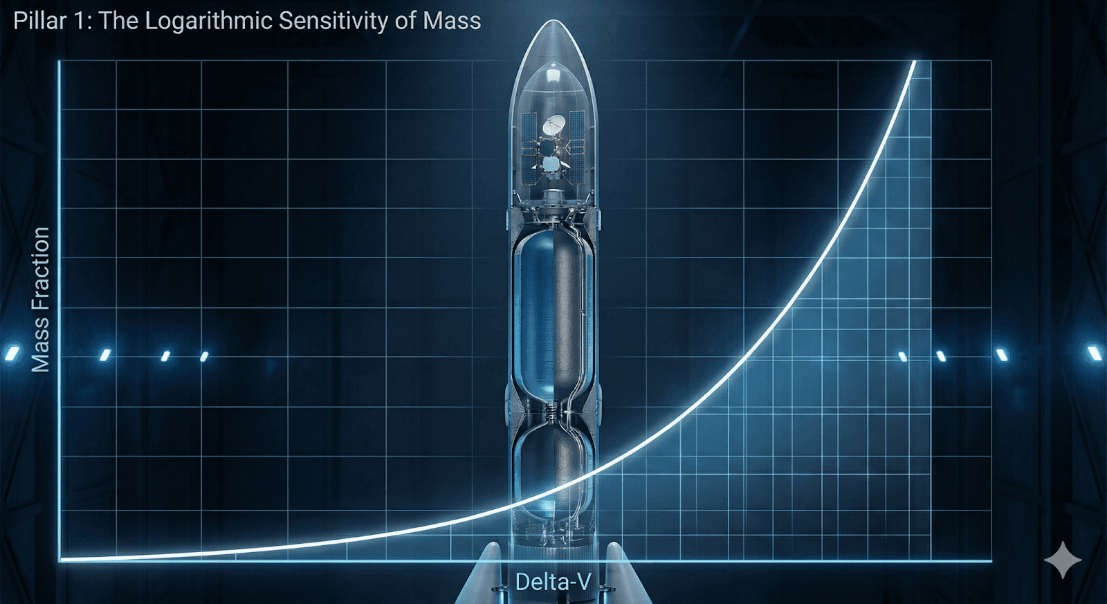
Pillar 1: The Logarithmic Sensitivity of Mass (The Rocket Equation)
The Constraint: The Tsiolkovsky Rocket Equation serves as the immutable gatekeeper of orbital mechanics:
Δv = Isp · g0 · ln(m0 / mf)
The tyranny here lies in the natural logarithm. To marginally increase Δv (velocity change), one must increase the mass ratio m0 / mf exponentially. Every gram of structural mass demands additional propellant to lift, which in turn requires more propellant to lift the propellant.
The Engineering Reality: This creates a sensitivity where a 5% increase in structural mass can effectively negate the vehicle's payload capacity. Engineers cannot simply "add material" to solve a stress concentration; they must optimize topology to shave grams while maintaining structural stiffness.
Technical Use Case: Topological Mass Optimization
The Problem: The interstage adapter for the launch vehicle is currently 15% overweight, threatening the payload margin. Manual iterations to find non-critical material are too slow.
The Agent Workflow:
User Prompt: "Analyze the Von Mises stress results of the interstage adapter in Ansys Mechanical. Highlight all regions with a Safety Factor > 5.0 and suggest material removal zones to reduce mass by 12%."
Agent Action: The Agent parses the result map, identifying "blue zones" where the material is bearing almost no load. It cross-references this with the buckling modes to ensure stability isn't compromised.
Resolution: The Agent identifies that the stiffener rings have excessive margin and suggests reducing wall thickness by 1.5mm. It executes the geometry change and re-runs the validation, securing the necessary mass reduction.
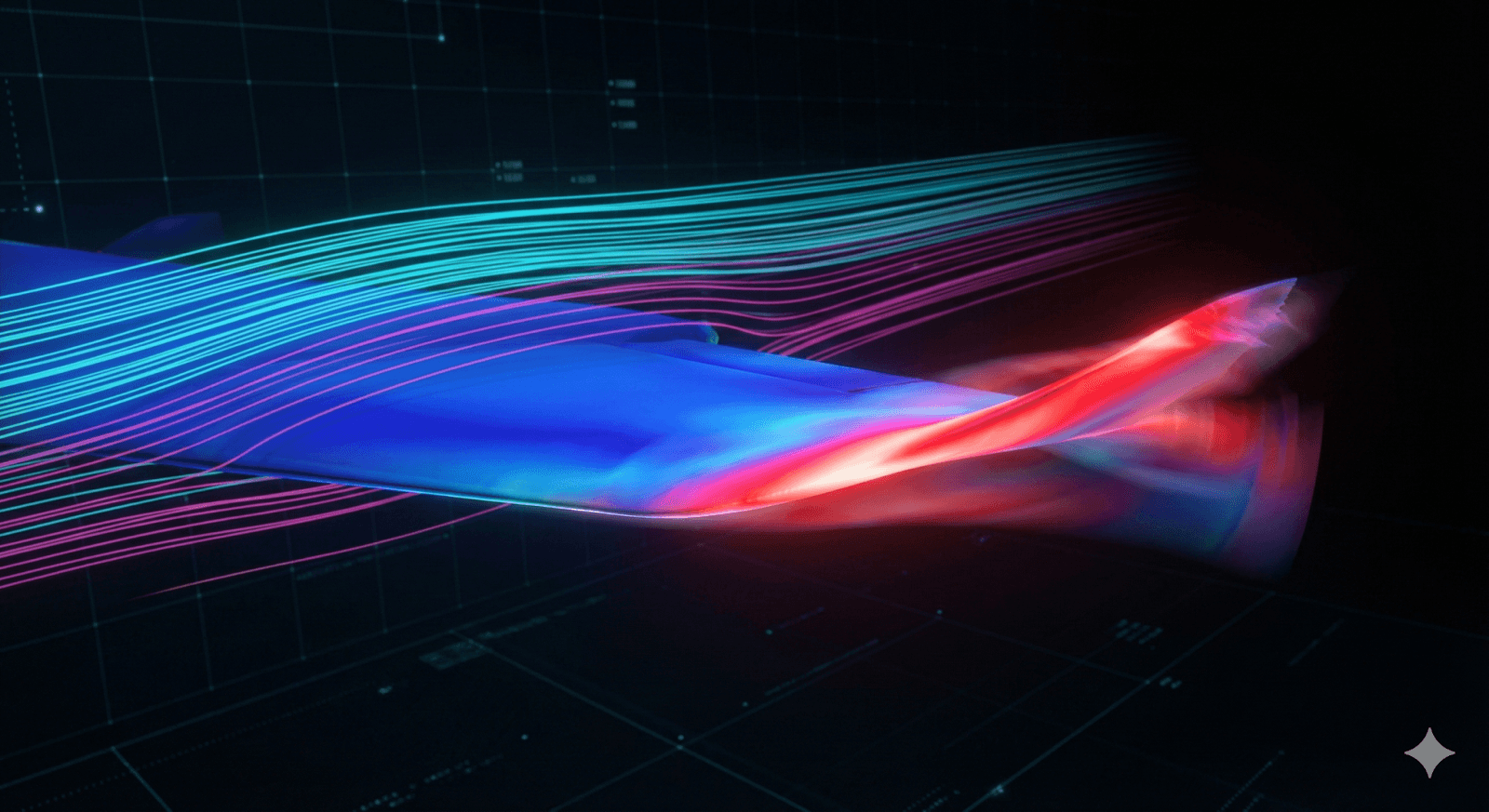
Pillar 2: Aeroelastic Instability (Flutter)
The Constraint: Fluid dynamics and structural mechanics are frequently compartmentalized in academic settings. In operation, they are a singular, coupled continuum known as Fluid-Structure Interaction (FSI).
The Phenomenon: Aerodynamic loads deform the elastic structure (wing or blade). This deformation modifies the local angle of attack, which in turn alters the aerodynamic load.
The Failure Mode: If the damping ratio of the structure becomes negative due to this feedback loop, the system undergoes a Hopf bifurcation known as Flutter. The structure begins to extract energy from the airstream rather than dissipating it, leading to divergent oscillations that can result in catastrophic structural failure within milliseconds.
Technical Use Case: Automated Flutter Analysis
The Problem: You need to verify the flutter margin for a new hypersonic fin design, but the aerodynamic pressure data is locked in the CFD solver (Fluent) and needs to be mapped to the Modal solver (Mechanical).
The Agent Workflow:
User Prompt: "Map the pressure field from the Mach 5 Fluent solution to the Mechanical modal setup. Run a pre-stressed modal analysis to check for coalescing frequencies."
Agent Action: The Agent scripts the import of the high-fidelity aerodynamic load, detecting and assigning the fluid-structure interface. It applies the pressure loads to the structural mesh and configures the damping parameters.
Resolution: The Agent successfully executes the coupled multi-physics simulation. It delivers a Campbell diagram showing the frequency evolution with speed, confirming the fin is flutter-free up to Mach 5.5.
Pillar 3: Hypersonic Aerothermodynamics
The Constraint: At hypersonic speeds (Mach 5+), the kinetic energy of the flow is converted into extreme thermal loads upon stagnation.
The Material Conflict: The materials required to withstand stagnation temperatures exceeding 2,000°C (e.g., refractory ceramics or C/C composites) often possess poor ductility or excessive density.
The Engineering Paradox: The vehicle must withstand thermal creep and ablation without compromising the precise aerodynamic outer mold line (OML). This forces engineers to implement active cooling systems (such as regenerative cooling in nozzles), introducing further complexity that re-triggers the mass constraints of the Rocket Equation.
Technical Use Case: Regenerative Cooling Verification
The Problem: The combustion chamber walls of the liquid rocket engine must be cooled by the cryogenic fuel, but optimizing the cooling channel geometry requires balancing pressure drop (fluid) against wall temperature (thermal).
The Agent Workflow:
User Prompt: "Set up a Conjugate Heat Transfer (CHT) analysis. Map the heat flux from the combustion gas side to the cooling channel wall. Sweep the channel hydraulic diameter from 2mm to 4mm."
Agent Action: The Agent configures the CHT interface, ensuring energy conservation between the solid and fluid domains. It automates the parametric sweep of the channel geometry within the CAD tool and updates the mesh for each design point.
Resolution: The Agent produces a trade-study plot showing Wall Temperature vs. Pressure Drop, allowing the engineer to select the optimal cooling channel size that prevents melting without choking the turbopump.

Front II: The Informational Tyranny (The Digital Thread)
If physics is the first hurdle, data management is the second. Engineers today spend up to 40-73% of their time acting as "data technicians"—cleaning geometry and formatting files. Nexus returns that time to you.
Pillar 4: Automated Design Engineering & DfX
The Constraint: The gap between "Physics Optimal" and "Manufacturing Capable." The "Silo"
Problem: Simulation engineers optimize for invisible fluids; Design engineers optimize for physical tooling. A common failure mode is the "over-the-wall" handoff, where analysts provide a "perfect" topology-optimized shape that is impossible to machine or requires weeks of manual CAD reconstruction to make parametric.
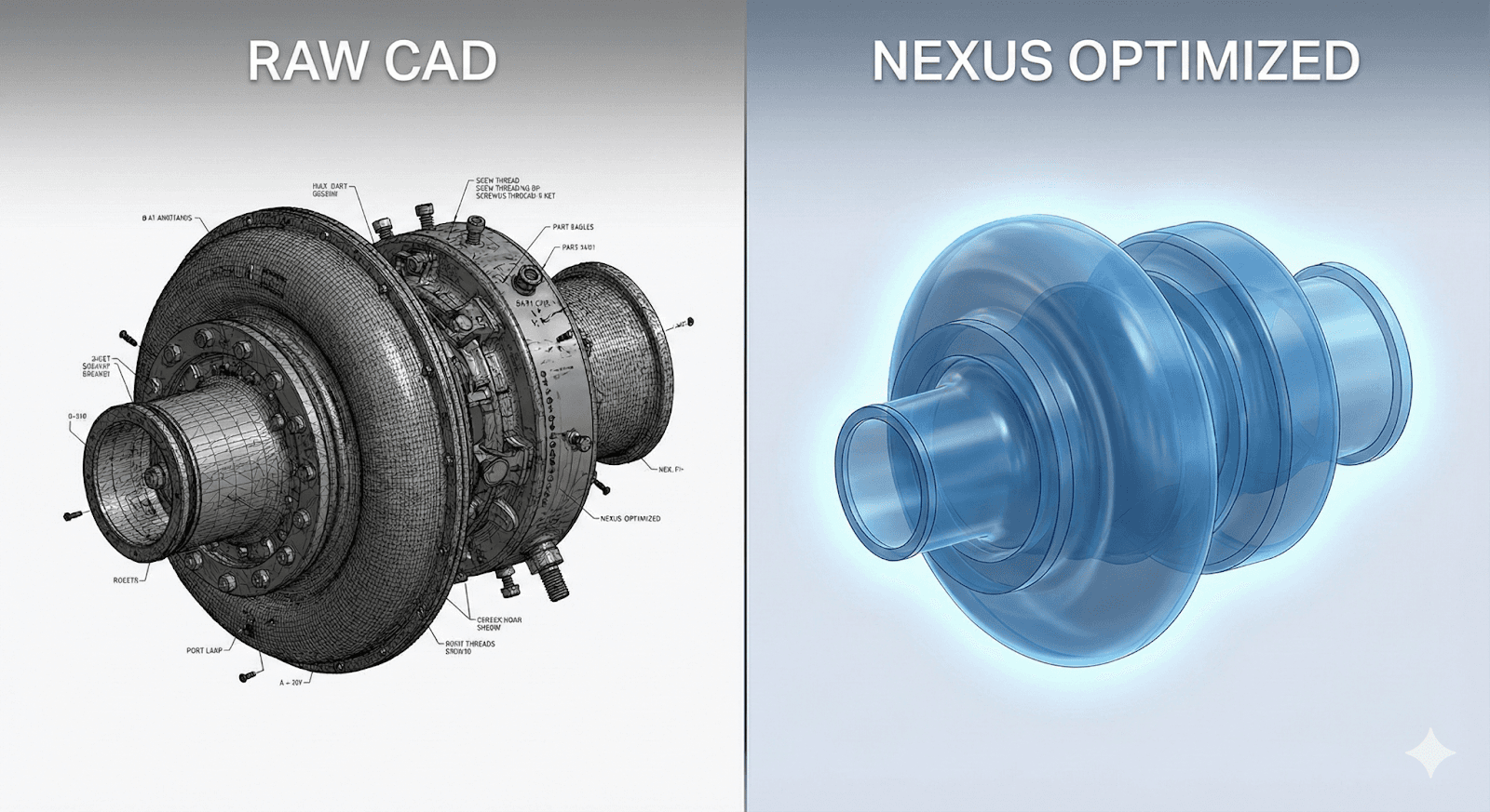
Technical Use Case: From "Organic Mesh" to "Parametric Solid"
The Problem: The structural team has provided a topology-optimized mesh for a titanium engine gimbal. The shape is organic, faceted, and lacks the precision features (drill starts, facing) required for the machine shop.
The Agent Workflow:
User Prompt: "Import the optimization mesh for the Gimbal_Mount into SolidWorks. Rebuild it as a parametric solid. Apply 5-axis milling constraints and run a DfM check for tool accessibility."
Agent Action: The Agent drives SolidWorks to reconstruct the geometry. It identifies the bounding volume, generates editable sketches and extrusions to approximate the organic shape, and applies manufacturing fillets. It then runs a DfX analysis, highlighting sharp internal corners that a CNC cutter cannot reach.
Resolution: The Agent delivers a fully parametric, editable CAD file—not a dead mesh. It automatically generates the 2D fabrication drawing with preliminary GD&T (Geometric Dimensioning and Tolerancing) applied to the bearing interfaces, reducing the "Design-to-Print" cycle from weeks to hours.
Pillar 5: The Interface Decoupling (Communication Blockers)
The Constraint: A complex vehicle is defined by thousands of interconnected parameters. If Team A (Propulsion) updates a variable, and Team B (Guidance) continues to work with the old value, the design diverges.
The "Silo" Problem: Communication latency. Teams often rely on manual handoffs—spreadsheets, emails, or weekly meetings—to synchronize data. This "information lag" means engineers are constantly simulating phantom vehicle configurations that no longer exist.
Technical Use Case: The Live Interface Control Document (ICD)
The Problem: The Propulsion team has updated the thrust curve efficiency based on a new nozzle test. The Trajectory team is unaware and is still running flight paths with the old Impulse data, leading to a critical mission timeline error.
The Agent Workflow:
User Prompt: "Scan the latest Propulsion subsystem output for changes in Thrust Coefficient. Compare this against the input parameters for the Trajectory simulation group. Flag any mismatches exceeding 1%."
Agent Action: The Agent acts as a real-time data broker. It identifies the parameter drift, generates a "diff" report between the two subsystem definitions, and auto-formats the new thrust data into the Trajectory team's required input schema.
Resolution: The Agent eliminates the communication blocker. It notifies the relevant stakeholders of the divergence and provides the corrected dataset instantly, ensuring the entire organization is building the same vehicle.
The Bottom Line: The Augmented Aerospace Engineer
Adopting Nexus AI Agents isn't just about upgrading your software; it's about upgrading your mental model of engineering.
By installing Nexus as a force multiplier, you address the silent killers of aerospace productivity:
Stop Clicking, Start Innovating: Delegate geometry cleanup to the Agent.
Bridge the Physics Gap: Automate the hostile coupling of Aerodynamics and Structure.
Continuously Audit Designs: Let the Agent fight the Rocket Equation for you.
See It Live
Theory is all well and good, but seeing your own physics solved autonomously is better. We have prepared a live demonstration environment featuring a real-world single-cell battery module.
In this session, we won't just show you slides; we will show the Agent in action:
Are you ready to stop wrestling with tools and start wielding them?