Feb 4, 2026
From Physical Problem to Validated Simulation: How AI Bridges the Translation Gap
By Maxwell Dylla
Every hardware engineer knows the frustration: you have a physical problem (battery cells swell during use), and you need to predict performance (will the housing crack?). But between the physical world and the simulation lies a translation gap.
How do you represent swelling in FEA? Which surfaces actually contact? What tolerances matter most? This translation - from physical phenomenon to validated simulation - is where most engineering time gets spent. And it’s where most errors creep in.
The Problem
Battery cells in consumer devices swell up to 9.5% volumetrically during use. This expansion creates pressure on the housing. Too much pressure and you risk housing deformation, screen damage, connector misalignment, and safety issues.
In practice, engineers rarely generate this test data themselves. Swelling characterization typically comes from cell suppliers, internal test teams, or third-party labs - often as a PDF report or spreadsheet that lands in your inbox. The challenge is translating this data into simulation inputs.
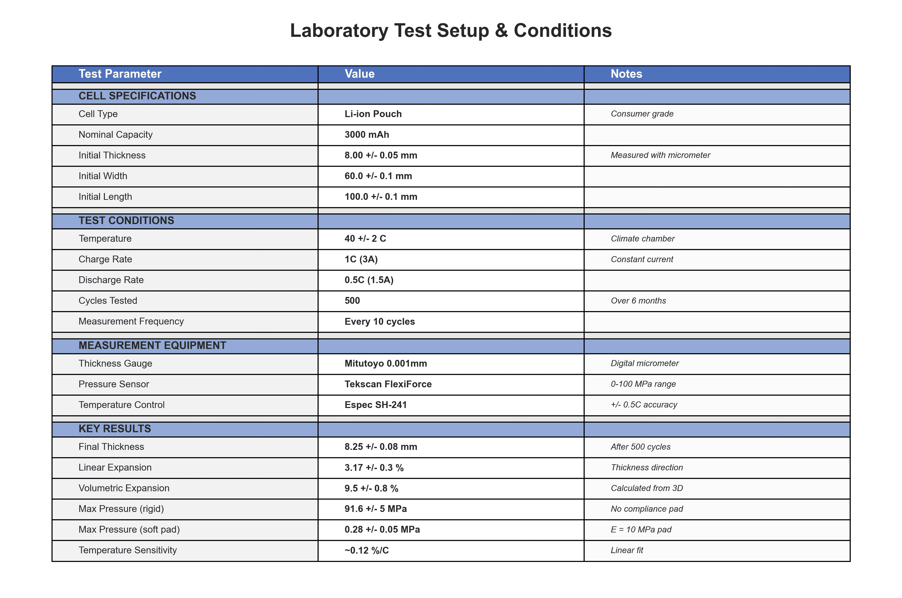
Laboratory Test Conditions: Example test report from cell characterization. This data - 9.5% volumetric expansion, 91.6 MPa pressure under rigid constraint, ~0.12%/°C temperature sensitivity - needs to be translated into FEA boundary conditions and material properties.
The numbers tell the story: after 500 charge cycles at 40°C, lithium-ion pouch cells exhibit 9.5% volumetric expansion. When constrained rigidly, this generates pressures exceeding 90 MPa - far beyond safe limits. The engineering question: how do we design the housing to accommodate swelling while maintaining structural integrity?
To answer this with FEA, you need to bridge multiple gaps. How do you represent “the cell swells 9.5%” as an FEA load case? There’s no standard approach. Which surfaces contact in a 3D assembly with housing, foam pad, and cell? That requires understanding spatial relationships. How do manufacturing tolerances affect the results? That requires parametric thinking.
The traditional approach takes weeks of trial-and-error, expert knowledge, and iteration. What if AI could reason through these gaps?
How AI Reasons Through the Translation
The first challenge is physics translation. How do you represent 9.5% volumetric swelling in FEA? There’s no “swelling” load type in the menu.
The AI recognized that swelling is fundamentally isotropic volumetric expansion - and that thermal expansion provides a perfect mathematical analogy. By calculating the right expansion coefficient (α = 0.0317) and applying a unit temperature change, the 9.5% volumetric expansion maps directly to a standard FEA capability. Temperature becomes just a convenient scalar field for representing expansion - no actual heat transfer involved. This is the kind of translation that typically requires deep FEA expertise.
The second challenge is understanding the 3D assembly. With three parts (housing, pad, cell) stacked vertically, you need to understand which way is up, where parts touch, and what the actual coordinates are.
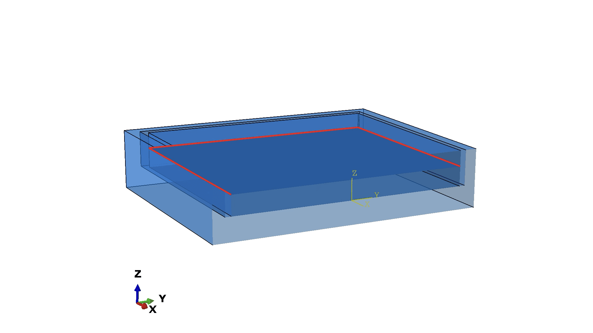
Assembly Cross-Section: Cross-section view showing the assembly arrangement. The vertical stack shows: Housing (bottom, Z=-6 to 0), Pad (middle, Z=0 to 5), and Cell (top, Z=5 to 9).
The AI used explicit coordinate checking at each step. What’s the Z-coordinate of the pad bottom? Z=0, matching the housing cavity floor. Pad top? Z=5, matching the cell bottom. Cell top? Z=9, which becomes the symmetry plane. This systematic verification prevents the compounding errors that plague manual setup.
The third challenge is contact mechanics - notoriously tricky to get right. The AI identified the load path (cell expands, pad compresses, housing reacts) and found contact pairs by checking Z-coordinates: pad top meets cell bottom at Z=5, pad bottom meets housing floor at Z=0. By understanding the physics - that the pad is trapped between cell and housing - the AI applied appropriate stabilization for convergence. Result: first-run convergence, no iteration needed.
Material selection matters too, and it’s about design intent, not just database lookup. The AI understood that the pad needs to be soft by design (E = 10 MPa) to act as a compliance mechanism absorbing the cell’s expansion. The housing needs to be stiff (E = 70,000 MPa) to provide structural constraint. With a stiffness ratio of 7,000:1, the pad absorbs nearly all the deformation - exactly as intended.
Finally, boundary conditions require understanding what symmetry represents physically. The AI reasoned through options: constraining the cell bottom would lock a contact surface that needs to move. Constraining the pad bottom would prevent necessary compression. The cell top at Z=9 represents the midplane of the full cell - the right place for a symmetry constraint.
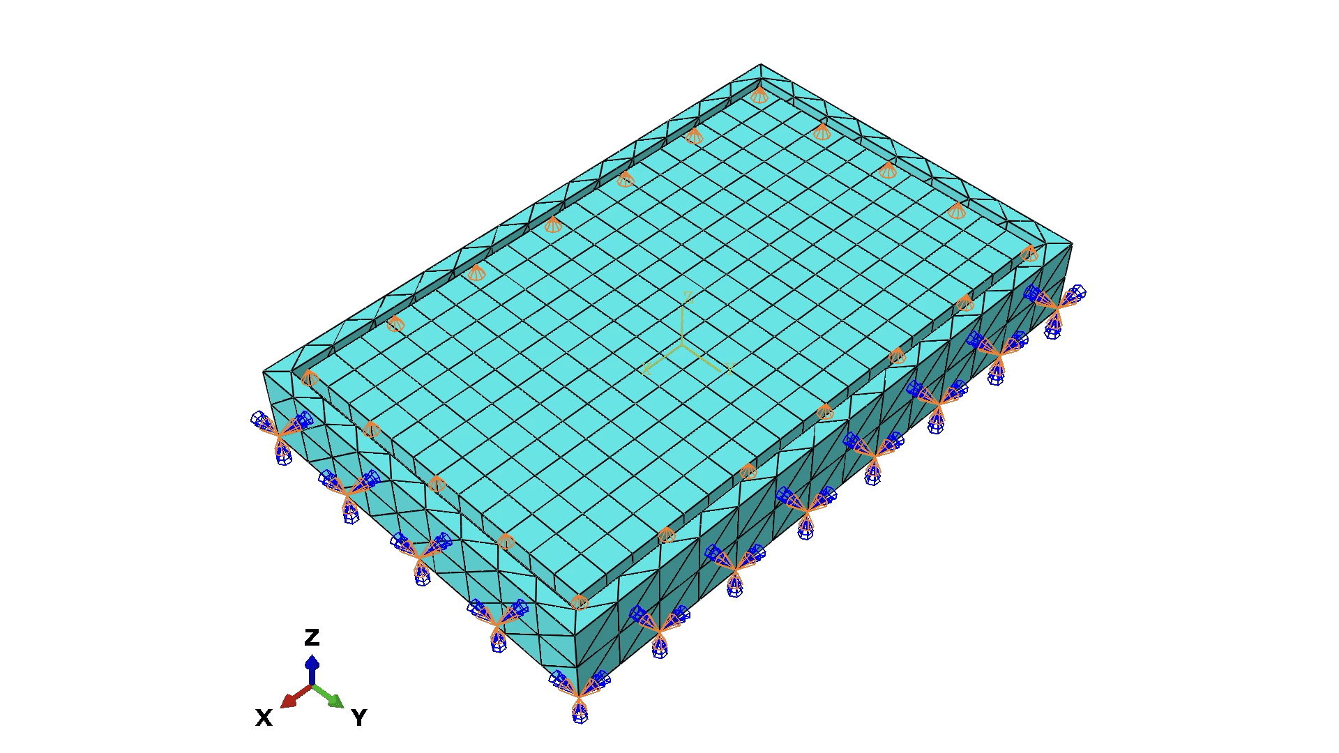
Symmetry Plane: The cell top (Z=9) represents the midplane of the full 8mm cell. The U3=0 boundary condition here prevents expansion through the symmetry plane while allowing lateral expansion.
Results and Validation
The simulation ran successfully on the first attempt. Maximum stress in the pad: 0.28 MPa, well below the 5 MPa safety limit. Pad compression: 0.13 mm. The strain contours show exactly what you’d expect - high strain in the expanding cell, moderate strain in the compressing pad, minimal strain in the stiff housing.
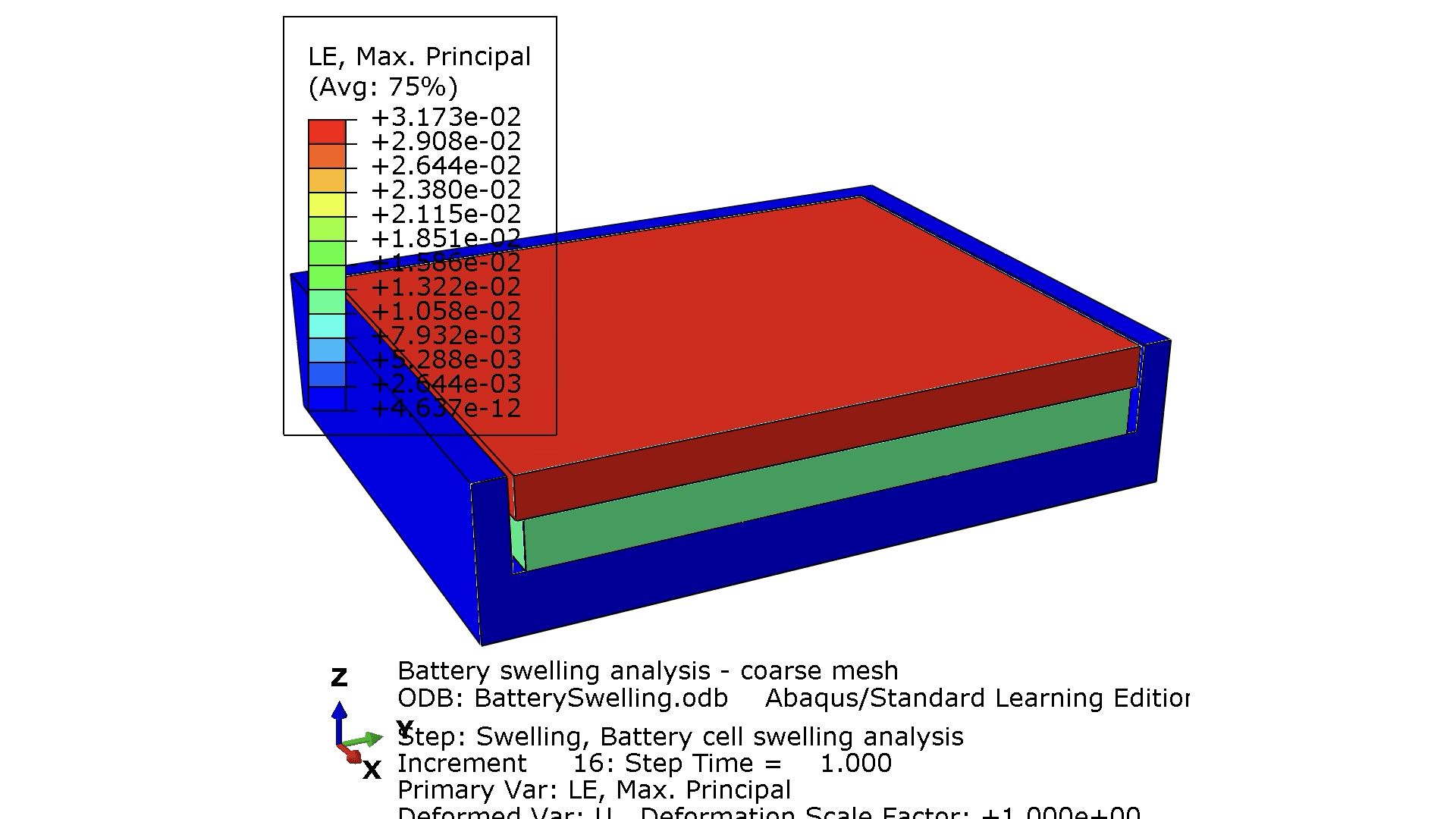
Strain Contours: Strain distribution showing the physics of the design. High strain in the cell (red/orange) shows expansion. Moderate strain in the pad (green/blue) shows compression. Minimal strain in the housing confirms it remains nearly rigid.
But how do we know these results are correct? Before running FEA, the AI built a first-principles analytical model treating the cell, pad, and housing as springs in series. The analytical prediction: 0.124 mm pad compression, 0.25 MPa stress. The FEA results: 0.13 mm and 0.28 MPa. Agreement within 5-12% validates both approaches. This is closed-loop verification - not blind trust in simulation, but engineering rigor.
The tolerance question matters too. What if the pad is thicker or thinner due to manufacturing variation? Running parametric studies shows that pad thickness has high sensitivity: a 0.5mm change produces a 25% pressure change. Housing stiffness has low sensitivity - it’s already so stiff that variations don’t matter much. This insight feeds directly back into CAD: tighten the pad thickness tolerance, relax the housing tolerance.
The Bigger Picture
The traditional workflow for a problem like this takes 1-2 weeks: translating physics, setting up geometry, debugging contacts, iterating on materials and boundary conditions, validating results. With AI assistance, the same work compresses to half a day - including analytical validation and tolerance studies.
That’s 5-10x faster, but speed isn’t the only benefit. You also get first-run convergence instead of trial-and-error, analytical validation instead of hoping the results are right, and integrated tolerance analysis instead of treating it as a separate effort.
You might think this only applies when building geometry from scratch. But even with CAD import, you still need surface identification, physics translation, contact pair definition, and tolerance analysis. CAD solves geometry creation, not physics understanding. These translation gaps that require engineering judgment are exactly where AI adds value.
The closed loop: CAD → AI → FEA → Results → Tolerance Analysis → CAD
Conclusion
The gap between physical problems and validated simulations is where engineering time gets spent - and where errors creep in. AI bridges these translation gaps by reasoning through physics, understanding 3D spatial relationships, identifying contact topology systematically, selecting materials based on design intent, validating results against first principles, and exploring tolerance-performance relationships.
This isn’t about replacing engineers. It’s about augmenting engineering reasoning - handling the tedious translation work so you can focus on design decisions. The battery swelling case study shows 5-10x faster iteration with physics validation and tolerance analysis. That’s the kind of acceleration that changes what’s possible in product development.
Working on complex simulation problems - whether it’s contact mechanics, multiphysics, or translating test data into validated models? We’d love to explore how AI can accelerate your workflow. Contact us to discuss your specific use cases.